Important: The information presented here is for the use of a qualified, experienced technician. Without the background knowledge which comes with training, you risk doing more damage then good to the copier & also risk your own safety. If you are not willing to take 100% responsibility for your actions, do not use the information posted here. Thank you. Read our conditions of Use for more information.
C123 Style - Fuser Rebuild Instructions (C123, 5225, and 5325 families)
C123 Style - Fuser Rebuild Instructions (C123, 5225, and 5325 families)
| Technical Specifications | |||||||||||||||||||||||||||||||||||||||||||||||||||||||||||||
|---|---|---|---|---|---|---|---|---|---|---|---|---|---|---|---|---|---|---|---|---|---|---|---|---|---|---|---|---|---|---|---|---|---|---|---|---|---|---|---|---|---|---|---|---|---|---|---|---|---|---|---|---|---|---|---|---|---|---|---|---|---|
Fuser Repairs: Xerox C123 & C118 styles… Servicing the Fuser Modules for the Xerox CopyCentre C123, C128, C133, & WorkCentre M123, M128, M133, Pro123, Pro128, Pro133… also the C118, M118, M118i… and the Phaser 5500:
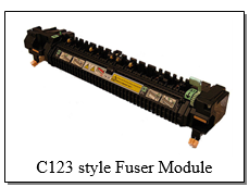
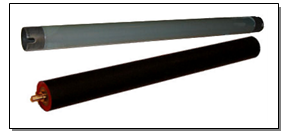
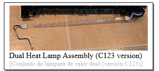
Here we go… More fuser modules worthy of service: C118 style and C123 style fusers are closely related to one another with a few significant differences. These fusers are rated for 175k but are reportedly needing service far before that yield is ever met. So… we’ll just have to take a look at how these things come apart. We’ll start with some notes on the differences between the C118 and C123 fusers, then we’ll hit on the disassembly process and finally end with a refresher on resetting the Fuser Codes from diagnostics. The C118 version of the fuser (126K16451 = 110 volt… 126K16461 = 220 volt) and the C123 style (126K16480 = 110 volt… 126K16490 = 220 volts). look very similar to one another and they come apart the same way. However, they are not even close to being interchangeable. The AC Connectors near the rear end of the fusers are pinned differently partly owing to the fact that the C123 version has dual heat lamp circuits as opposed to the C118’s single lamp circuit. As far as the parts are concerned… At first glance it appears that the heat and pressure rollers would probably be the same part however this proves to be completely untrue. The C123 and Phaser 5500 versions use a thin-walled steel core roll which allows it to reach operating temperature very rapidly while the C118 has a much thicker walled aluminum core. The Pressure Rolls are larger diameter in the C123 version. Picker Fingers, and Fuser Drive Gears are interchangeable. There are two Thermal Fuses (thermostats) in the C123 fuser and only one in the C118. The C123 also has two Thermistors (the C118 shares the centrally located one but is missing the one which is closer to the rear end of the fuser roll). The Heat Lamp Assembly in the C123 is one of the most exotic looking Heat Lamps. It is basically two lamps joined together at either end. The two halves of the lamp assembly are on separate input circuits but share the same return line which goes through both thermal fuses. The C118 has ends which would remind you of the C123 but with only one lamp. More recent models include the 5225 family which uses an interchangeable fuser with the C123… Then the most recent 5325 family has some changes to the fuser itself even though the heat roll and pressure rollers are interchangeable. Below are the various version:
126K16480, 126K16481, 604K20342, 604K20343, 604K20344, 622S00191
126K24980, 126K24981
126K29391, 126K29392, 126K29393, 126K29394, 126K29395
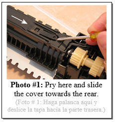
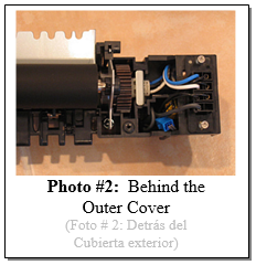
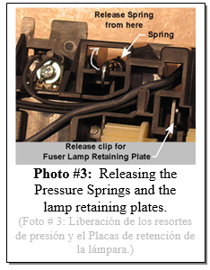
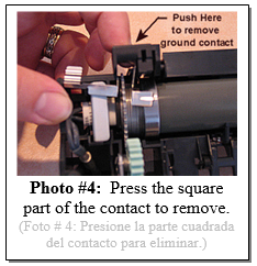
I found these fusers to be typical as far as form and function but quite different from most of the others we’ve covered in the past when it comes to disassembly procedure. To take them apart you’ll end up taking the Pressure Roll off before you can get anywhere near the Heat Lamp Assembly or Heat Roller. This means that they will require a little more time than many of the other fusers in the Xerox lines. Still, you should remain undaunted. Once you take one apart and reassemble it, like most things, it’ll get far easier the second time you do it. According to the OEM Parts List, Xerox appears not to spare any of the parts in the fuser (you’d have to buy the entire fuser even if just a gear breaks). So, you’ll need to rely on the generic rollers which are proving to work most excellently. Now for the disassembly procedure… lets start with getting oriented. In the procedure, I’m going to refer to the “outer face” which will be the part of the fuser which faces out when you see it in the machine. If you’re looking at the Outer Face, the two thumbscrews and the green jam release lever will be facing you. The Bottom of the fuser has the two thumbscrews, the Idler Gear pair and the thermal fuses. The Rear of the fuser is the end with the Fuser Drive Gear. Now to it… Disassembly Procedure: 1. We’ll start with accessing the Thermal Fuses on the bottom of the unit. There’s a sliding cover. You’ll have to use a small flat-head screwdriver to pry up on a catch (see Photo #1) and then slide the cover towards the rear end of the fuser (the end with the gears). 2. The Thermal Fuses (C123 has 2 of them, C118 has only one) are now easily removed (two screws on each). If any lamp circuit is out, you can measure these fuses in place for continuity and replace whichever one shows no continuity. 3. Remove the Outer Cover from the Outside Face (2 screws… one at the front, one at the rear end). Hinge the cover down and remove it. This exposes the Pressure Roll and the Heat Roll can be seen behind it. You can also get a look at the end of the Heat Lamp Assembly, and the Fuser Drive Gear. You also get a peek at one of the troublesome things about the Heat Lamp Assembly… the leads at the rear end go directly into the pins on the AC Connector so you’ll need to detatch the pins from the AC Connector if you ever need to replace it. (See Photo #2). 4. Next you’ll be gunning for the Pressure Roll Assembly… This can be done safely by placing the assembly outside-face down so that the metal pressure arms are down on a hard surface. Keep pressure down on those arms while you use a springhook or the blade of a small flat-head screwdriver to lift the springs off of the plastic on the opposite side (see Photo #3). With the pressure off, the arms will hinge away and allow you to take the Pressure Roll out of its plastic line bearings. 5. Remove the metal Entry Baffle. This requires releasing an extremely delicate little plastic clip at the front end. It is best to pry this plastic clip lightly from the outside of the entry baffle just enough to clear the metal and then slide the metal baffle out at that end first. I broke my first test subject by pushing it too far from the inside. The good news is that once the outer cover is back in place, it will hold the metal baffle in position even if you broke the plastic retaining clip. 6. Now you’ll be prepping for removing the Heat Roller and the Heat Lamp Assembly. First remove the ground contact near the front end. Press the square part in and pay attention to how it seats so you can get it right at reassembly (see Photo #4). You’ll also need to remove the green jam release lever / gear to make room for the Heat Roll to come out. It is held by a single e-clip. Don’t lose the little tension spring for the lever / gear. One more thing to do to prepare… Release the front Fuser Lamp lead. It is connected with a spade connector to the front Thermal Fuse. 7. Now for the tricky part… you’ll be removing the fragile lamp assembly and the roller together. Release the front and rear seating clips from the Heat Lamp’s metal Retaining Plates so that they’re loose. (refer back to Photo #3). You’ll then work the Heat Roll Assembly and the Heat Lamp Retaining Plates out a little at a time from either end. Pay close attention to the Heat Lamp Assembly to make sure you don’t put any stress on it or it will certainly shatter. 8. Each thermistor (the C118 has only one) has one screw securing its head and then wires go to a tiny connector which seats in a larger connector which then had wires continuing to the AC Connector. The blue connector goes to the central Control Thermistor which has longer wire leads by necessity. The yellow connector goes to the Overheat Thermistor located near the rear end of the Heat Roll (this is the thermistor which is missing from the C118 version of the fuser). 9. When it comes time to reassemble, you’ll need to tie back the five Picker Fingers with rubberbands or tape, or else they’ll get in your way and endanger the Heat Roll’s surface.
That’s it on the procedure. Now for a bit of a refresher on fuser related Status Codes and how to reset them. We had covered all this in a series of 4 previous articles (two in the May and June 2007 ENX articles about the C118 style followed closely by two from July & August ENX articles on the C123 style machines). Status Codes and Diagnostic procedures are thoroughly different for the two styles of machines.
Fuser Related Status Codes & how to reset them:
C123 style (C123/128/133, M123/128/133, Pro123/128/133)
* C123 style: Resetting Fuser Codes (010-320, & 010-327) Accomplished by resetting NVM code 744-220 to ‘0’… First enter UI (User Interface) Diagnostic Mode: Hold down the ‘0’ button for 5 seconds and then press the ‘Start’ button while still holding the ‘0’ button. The machine will prompt you for a Password. Enter the default Access Number: ‘6789’ and press “Confirm”. The colors on the display will be reversed to indicate that you’re now in diagnostic mode. Next press the “Log In/Out” button on the Control Panel. Select ‘System Settings’, ‘Common’ Settings, followed by ‘Maintenance / Diagnostics’. Now you will find the main menu includes one choice called “NVM Read / Write” (NVM is Non Volatile Memory)… Now you can enter your “Chain-Link” code (in this case 744-220) and press ‘Confirm / Change’. The current value will appear (if the machine is in a fuser fault condition, the value will be set to “1”). Select the “New Value” column and input your new value (‘0’). Select “Save” and the new number should now appear in the “Current Value” column. You can turn the power off and back on at this point. The machine will attempt to warm up the fuser again. If the condition which caused the fault in the first place is still happening, the Status Code will return after a few minutes of attempting to warm up.
C118 style (C118, M118, M118i)
* C118 style: Resetting Fuser Codes (U4-1 or U4-2): Enter diagnostics (from the powered on state, hold down the ‘0’ button and then press ‘Start’. The display will change to opposite colors to show you it’s in diagnostics)… Select ‘Chain-Func’ in the ‘CE Setting’ screen by using the ‘Select’ button, followed by ‘Enter’. Select “NVRAM R/W”. Enter the “Chain” (in this case ‘50’). Next select “Func” (function) by using the “Select” button. Enter the “function” (‘20’ if you’re clearing a U4-1 code or ‘19’ for clearing a U4-2 code) followed by ‘Start’. The current value for that memory code (50-20 or 50-19 in these cases) will appear in the “Read” column (if the machine is in a U4-1 or U4-2 status condition, the value will read as ‘1’). Change the value by pressing the “Select” button at the “Read” column to switch to “Write”. Enter a ‘0’ for the new value, and then press ‘Start’. Finally, select “Write NVM”.
You’ll probably be well served by being able to test the lamp and thermistor circuits from the AC Connector so you know what you’re looking to replace before you even rip into the fuser.
Also we’ve found out that on the WC-5335 Family in particular, it’s critical to update the firmware on the machine, because they’ve corrected a few problems relating to the fuser. One known problem results in the fuser running too hot. The toner will ravel on the page if you smear at an area of heavy background. Then the toner will start to offset on the pages and on the thermistors… which makes it get even hotter until the black sleeve-like coating of the pressure roll sticks to the heat roll and will peel off in patches. The book says the WC-5325/5330/5335 machines should all be updated to software version 53.30.11 or higher. You can go and download the firmware from support.xerox.com (that is a great resource for anything which the customer needs to do, as far as changing administrator settings, or reloading firmware, etc). On the support site, you will enter the model of the machine and choose either “support” or “Drivers and Downloads” for the correct model from the list that appears. In this case choose “Drivers and Downloads” and scroll down to the bottom where the Firmware choices are found. Download the zip file and unzip it so you can see the .bin file which the machine needs. The support site does explain how to upgrade the software from the Network, but I noticed that the instructions about how to install the software using the USB way of doing it is missing (usually they include a pdf or a text read-me file with instructions in the zip file, but it is missing in this case), so… here is how that goes:
UPDATING SOFTWARE ON 5335 Family from a USB Flash Drive: Create a folder in the USB Flash Drive and name it "DWLD". Copy the .bin file obtained from the support.xerox.com website (comes in a zip format, unzip it and copy and paste it into the new folder). Make sure USB printing is enabled, and then turn the machine off completely (turn off both power switches (one is inside the front cover)). Plug in the USB flashdrive into the USB connector on the Control Panel (if available). (note that If the machine doesn’t have a USB connector on the Control Panel you will need to use the top one on the ESS PWB chassis on the right at the rear of the machine (it may have a metal shield held by one screw blocking). Next, hold down the "Energy Saver" button while powering on the machine. Keep holding the button till the message "Download Mode" appears. It will eventually say "Transferring" and later "Processing 1 / 7". When the download is complete, the machine will reboot itself, a progress bar will show up, and the machine will come to ready. Check the Software Version by pressing "Machine Status" and then selecting "General Information" followed by “Software Version” to make sure the upgrade was successful. Now you can power down and remove the USB Flash Drive.
To clear some fuser fault codes and also to reset the HFSI (High Frequency Service Item) counters you’ll need to go into the Diagnostic Mode. Getting into the Diagnostics is slightly different on the older models (C123 Family), but it’s still pretty close: Entering UI (User Interface) Diagnostic Mode: From the powered on state, hold down the ‘0’ button for 6 seconds and then press the ‘Start’ button while still holding the ‘0’ button. The machine will prompt you for a Password. Enter the default Access Number: ‘6789’ and press ‘Confirm’. The display will acknowledge that you are now in diagnostic mode (on the C123 Family, the colors on the display will reverse). Next press the “Machine Status” button (or “Log In / Out”for the C123Family). Select the “Tools” tab, then: ‘System Settings’, ‘Common Settings’, ‘Maintenance / Diagnostics’. This will bring you to the Main Menu where you’ll find the memory settings (NVM) and lots of other important stuff. The HFSI counters (for resetting fuser count and other High Frequency Service Items is found in “Adjustments / Others”.
Now let’s have a peek at a list of the fault codes which have to do with the fuser.
Fuser Related Status Codes & how to reset them:
C123 & WC-5230 Families: (C123/128/133, M123/128/133, Pro123/128/133, WC-5222/5225/5235)
WC-5335 Family: (WC-5325/5330/5335)
* Resetting Fuser Codes (010-320, 010-327, 059-315, & 059-317) Accomplished by resetting NVM code 744-220 to ‘0’ (OR 744-005 for WC-5335 Family)… First enter UI (User Interface) Diagnostic Mode (read above for details): Once you’re in the Maintenace / Diagnostics Menu, you’ll see among other things a choice called “NVM Read / Write” (NVM is Non Volatile Memory)… Now you can enter your “Chain-Link” code (in this case 744-220, OR 744-005 for WC-5335 Family) and press ‘Confirm / Change’. The current value will appear (if the machine is in a fuser fault condition, the value will be set to “1, 2, 3, or 4 depending on the exact fault). Select the “New Value” column and input your new value (‘0’). Select “Save” and the new number should now appear in the “Current Value” column. Choose “Call Closeout” to reboot. The machine will attempt to warm up the fuser again. If the condition which caused the fault in the first place is still happening, the Status Code will return after a few minutes of attempting to warm up.
If you have a stubborn machine which keeps timing out when it’s turned on in the mornings, a few folks have reported that changing the NVM memory setting 744-043 to “1” extends the allowable warm up time. This helps to get the machine to be more forgiving. Still it’s important that the owner of the machine keep it in a room which doesn’t get too cold at night.. If the room is too cold when they turn the machine on, it’ll likely go into a fault code which requires a tech come turn the code off from diagnostics. You’ll want to test the fusing closely after changing any fuser setting to make sure it still fuses under various circumstances because variations on the firmware could make one machine behave slightly different from another.
There’s one more thing which will prove helpful in checking a fuser you’re about to rebuild. You’ll want to know which pins are for which circuits within the fuser. There are two Heat Lamps which are actually joined into one lamp assembly to check out. Those two both share a common return lead which goes through the Thermostat (thermal fuse). If the fuser overheated severely enough, the Thermostat will be blown and will need to be replaced. There are also two Thermistors: A Rear Overheat Thermistor, and a Center Control Thermistor.
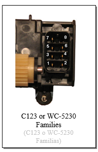
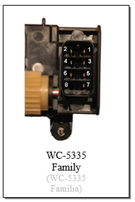
Here are the pin-outs for each of the fuser components for the C123 & WC-5230 Families vs. the WC-5335 Family.
Note that the C123 and WC-5230 Families are interchangeable, but on the WC-5325 the pin-out is completely different and they’ve gone so far as to flip the connector over. Check out the two photos on the right. Either of the two Heat Lamp circuits should measure 100 ohms or less and the Thermistors should read over 3K ohms if they’re good. Each heat lamp circuit goes through the same Thermostat (thermal fuse) and back through the same common lead.
That should bring everyone up to speed on the newer fusers in this “Style” of Xerox copier. You can get to the Fuser Rebuild Instructions by looking up the 2008 ENX article from the archives. It is pretty straight forward although as usual it is helpful to have the instructional to help shorten the learning curve a bit.
Enjoy rebuilding these fusers everyone!
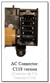
On the C123 version, there are slots for 8 pins (2 rows of 4 arranged vertically). Pin 7 is on the upper left and Pin 8 on the upper right is empty. Pins 7 & 1 are one of the two Heat Lamp Circuits. Each Heat Lamp Circuit goes through its respective half of the Heat Lamp Assembly, and then through both thermal fuses to the return wire (pin 7 is the return wire which is common to both heat lamp circuits). Pins 7 & 3 are the other Heat Lamp Circuit. If either Thermal Fuse is blown, neither lamp circuit will conduct. If one circuit measures good and the other measures bad, then the Heat Lamp Assembly must have failed. The Thermistor circuits for the C123 are between Pins 2 & 4 and Pins 5 & 6. If you set your meter to 200K ohms, you can measure the Thermistors… they should measure a high resistance and then if you were to warm up the Thermistor’s head, the resistance should begin to drop. These Thermistors are unusual in that the heads are naked (no yellow kapton tape). The C118 fuser’s AC Connector is shaped the same as the C123 version (slots for 8 pins) however there are only 4 pins actually present and they numbered the pins differently for this one. On this one, Pin 2 is in the upper left corner and Pin 1 is in the upper right. On this connector, Pins 1 & 3 form the Heat Lamp Circuit. The Thermistor Circuit is between Pins 2 & 6.
Hope this turns out to be valuable information for you. It’d be a shame to replace one of these fusers and then throw out or return the used one without at least inspecting it for the possibility of fixing it for the next customer who needs one. Be a green-tech and fix’em when you can. Happy Repairs everyone!
Britt works for The Parts Drop, a company whose primary business is providing parts, supplies and information for Xerox brand copiers, printers and fax machines. You can find more information, including many of Britt’s past ENX articles on their website, www.partsdrop.com. If you’d like to read more about Xerox brand office equipment, there’s also a complete listing of past articles under contributing writers on the ENX website (www.ENXMAG.com). |

