Important: The information presented here is for the use of a qualified, experienced technician. Without the background knowledge which comes with training, you risk doing more damage then good to the copier & also risk your own safety. If you are not willing to take 100% responsibility for your actions, do not use the information posted here. Thank you. Read our conditions of Use for more information.
DC250 / DCP700 / 550 etc - 2nd BTR Rebuild Instructions
DC250 / 550 / 700 / J75 - 2nd BTR Rebuild Instructions
| Technical Specifications |
|---|
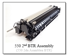
Xerox® 550 & DCP 700… Rebuilding the 2nd BTR Roll Assemblies (DC250 style) - Time and Patience Xerox Docucolor® 240, 250, 242, 252, 260, WorkCentre® 7655, 7665, 7675, 7655, 7665, 7675, Xerox® Color 550/560/570, C60/C70, DCP-700/700i/770, Color Press C75/J75
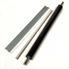
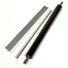
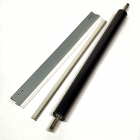
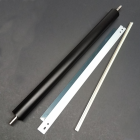
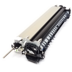
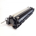
A bit of time and a healthy dose of patience (as well as a few replacement parts) are all that’s needed to rebuild one of the DCP700 or Color 550 2nd BTR Roller (Transfer Roll) Assemblies. The first few techs who rebuilt these reported that what looked like a fairly easy repair, took them hours to figure out. I have been wanting to write an article on these for some time now. For this one I needed my brother Kurt’s help. He showed me how these come apart. With his guidance in the form of this article, this repair will be far more approachable.
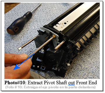
We’ve come to realize that, as is true in most things, with experience comes ease of repair. There are a few tidbits of knowledge which make this procedure far easier. One of the keys is to slide the Pivot Shaft out through the front end of the unit rather than the rear end. (The temptation is to leave a pair of e-clips on the shaft and slide it out through the rear end… but as it turns out, there’s a ground clip inside which you need to sneak the shaft past. The rear end of the shaft is rounded to help get it by that ground point. You’ll also see there are parts which don’t need to be removed at all... in particular the Cam Shaft and all the hardware on that part of the assembly.
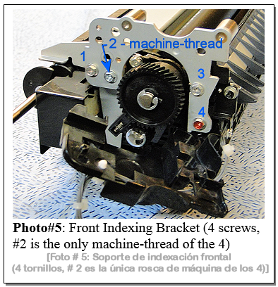
There are two types of screws on this assembly… long-plastic-thread screws and short-metal-thread screws. It’s important to put the correct kind of screws back in the right spots or you’ll run into problems. The instructions below will mention which type of screw is in each position.
There are 4 versions of this assembly depending on which model machine you’re working on… all are similar to one another but there are differences as well. They’re not interchangeable.
TOOLS NEEDED:
PROCEDURE:
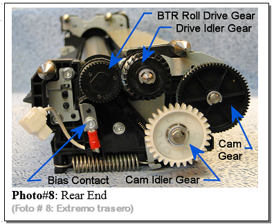
NEXT for the rear end (see Photo #8):
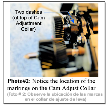
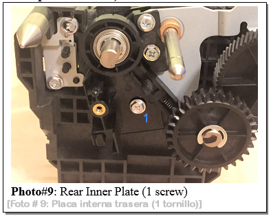
10. Also remove the BTR Drive Idler Gear (DC250BTRDIG or DC700BTRDIG) from its shaft (1 E-clip) and then remove 2 other E-clips from the same shaft behind where the gear was mounted. 11. Remove the Rear BTR Roll Bias Contact (1 screw – short machine thread)(Refer to Photo #8) 12. Now you can remove the Rear Cam Adjust Collar and its bearing from the BTR Roll’s shaft (1 E-clip) 13. Next take off the Rear Inner Plate This is the part which the bias Contact was attached to… it also holds the Rear Cam Adjust Collar’s Indexing Pin (as with the one on the front end…be very careful as the indexing finger and its spring can pop off and get lost easily). (1 screw, plastic thread)
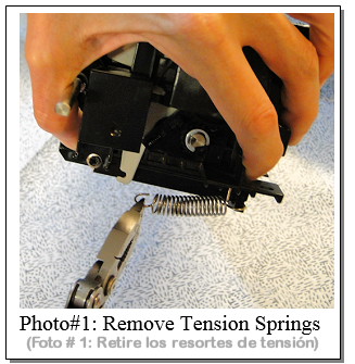
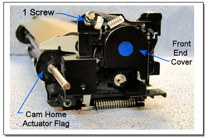
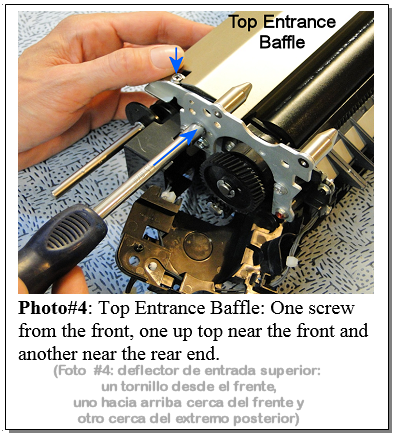
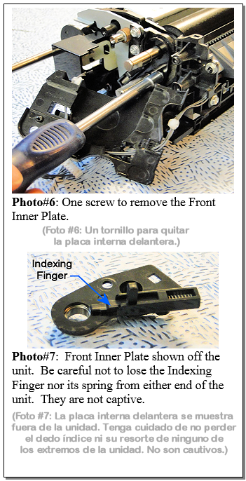
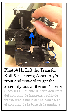
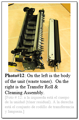
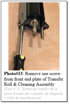
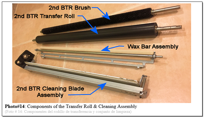
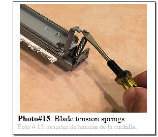
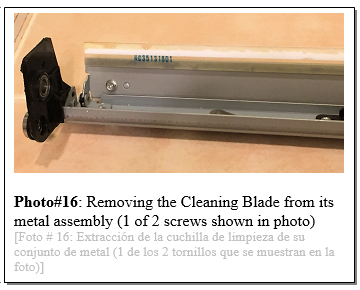
14. Slide the Pivot Shaft out through the front end. Note that the metal Pivot Plates at both the front and rear end will fall off at this point. (refer to Photo #9 and 10) 15. Lift the Transfer Roll & Cleaning Assembly out of the body of the unit. You can lift the front end up and out first (see Photo #11)… Be gentle with the fragile foam gasket strip on the front end which needs to remain intact. Also watch the Mylar Recovery Blade which is along the right side of the assembly, next to the Transfer Roll. 16. Vacuum out the waste toner in the body of the unit. (see Photo #12) Again, be gentle with the Mylar Recovery Blade. 17. Remove the Front-End Cover from the Transfer Roll & Cleaning Assembly (1 screw) (see Photo #13). With this cover off, you can remove the Transfer Roll, the Cleaning Brush, and the Wax Bar Assembly from the metal framework of the Cleaning Blade Assembly (see Photo. #14) 18. Check the wax bar. The old wax bar’s metal plate is adhered to the rest of its framework by double sided tape. Be gentle with this piece… they can sometimes crack, which is ok, as long as all the pieces remain in place on the metal plate. This Wax Bar serves to help lubricate the Cleaning Brush. 19. Remove the tension springs on the Cleaning Blade Assembly (one at the front end and one at the rear end). (see Photo #15) 20. Pivot the Cleaning Blade Assembly open and remove the 2nd BTR Cleaning Blade (2 screws). (see Photo #16) 21. Check the condition of all of the gears. If any look worn out or damaged, replace them… see the information which follows for identifying the correct part numbers and names for each of the gears. Two are for the 2nd BTR Roller Drive… and two are for the 2nd BTR Camming. 22. Reassemble everything. Take your time and make sure things fit right against each other. Don’t force anything… there are a few places in this unit (especially near the cam plates of the Transfer Roll) where there are delicate parts in harm’s way. If something is not quite in the right spot and you push too hard against it, it’d be easy to damage some of these parts. Refer back to the disassembly procedure and the photos to help see how everything should go and pay attention to which screws go where (machine thread vs. plastic thread is important).
That’s a wrap. Hopefully the procedure helps to make tackling one of these units less intimidating & less time consuming. Happy repairs folks!
See also in "Related Products" the Technical Information Article which helps you identify the part numbers for all of the gears on the 4 versions of the 2nd BTR Assemblies. |
| Information Reference |
| Author: Britt Horvat This is one of our own Partsdrop Write-ups. We hope you find it helpful! |

