Important: The information presented here is for the use of a qualified, experienced technician. Without the background knowledge which comes with training, you risk doing more damage then good to the copier & also risk your own safety. If you are not willing to take 100% responsibility for your actions, do not use the information posted here. Thank you. Read our conditions of Use for more information.
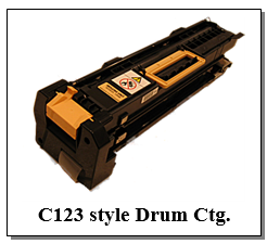
C123 Style - Drum Cartridge Rebuild Instructions (c123, 5225, and 5325 families)
| Technical Specifications | ||||||||||||||||
|---|---|---|---|---|---|---|---|---|---|---|---|---|---|---|---|---|
Rebuilding Xerox® C123 style Drum Cartridges (C123CRK): Xerox® CopyCentre® C118, C123/128/133 & WorkCentre M118/118i, M123/128/133, Pro123/128/133 (013R00589), and WC-5225/5230/5235 (101R00435), (5500CRK): Phaser® 5500/5550 (113R00670), & (5325CRK): WC-5325/5330/5335 (013R00591)
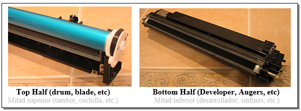
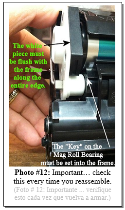
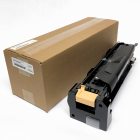
There are plenty of the C123 style machines out there, both in the hands of the Dealerships and in the aftermarket as well for the older families in this “style”. They’re reported as performing very well in the field. They don’t break down all that much from what I’m told, so that makes servicing the cartridges and modules that much more important. This is another example of one of those “win-win” situations. You can rebuild a cartridge, save your customer money, while making a healthier profit for yourself… all while keeping the used cartridge out of a landfill. I’ll start with a bit of an introduction to the cartridges along with some details about them and then get into the disassembly procedure highlighting any tricks or possible pitfalls to avoid. Like many of other models, the C123 family and the WC-5225 family (and also the Phaser 5500 family) machines employed RF (Radio Frequency) CRUMs (Customer Replaceable Unit Monitor chips). This type of chip does not make any physical or electrical contact with the machine at all. Instead a radio emitter / reader board waits for the CRUM on the cartridge to slide into close proximity. That board can read the chip’s type and copy count, and then write to the chip to update the copy count (the count is kept on the cartridge’s CRUM). The newest members of this “style” are the 5325 family. Here they abandoned the RF CRUMs and these have the CRUM in the front end of the unit where it does make physical contact. When you start taking one of these Drum Cartridges apart, you’ll find that it has two halves… The lower half is the Developer Unit with its augers and magnetic roller. The machine is dual component, so there is developer material in there. The upper half houses the Charge Roll, Drum and Cleaning Blade. The original cartridge’s reorder number is 13R589 (013R00589): for CopyCentre C118, C123, C128, C133, WorkCentre M118, M118i, M123, M128, M133, Pro123, Pro128, Pro133. Good for “up to” 60,000 pages (I will explain below), these cartridges sell for around $230.- retail. For some reason, if you run short runs of 1 or two pages at a time, the yield is a lot lower (as low as 32K). The 60K stated yield is based on running 6 pages on average each time the machine is used… if you were to run very long runs (500 to 1000 pages per run), the yield supposedly climbs up to nearly double the stated yield. A cousin, the Phaser 5500’s cartridge (113R670, retails for around $280.-) it is the same as far as procedure goes. Same is true for the WC-5225/5230/5235 (101R00423). Each has a unique CRUM chip, so they are not interchangeable. The newest models: 5325/5330/5335 use a new part number 13R591 (013R00591)… here the difference is the CRUM chip as was mentioned earlier. At the end of the procedure you’ll see how to replace the CRUM chips in each of these families. The procedure for disassembling / cleaning and reassembling a C123 Drum Cartridge has a few tricks to it. I did like that they used the same size and type of screw throughout the cartridge (Phillips head)… that was nice of ‘em. It’s a fairly easy cartridge to get into but the reassembly requires paying attention to a few details. Especially there are tricks to the Lower Half (Developer station). Let’s tackle the procedure…
PROCEDURE (Part 1) – Separating the Top and Bottom Halves:
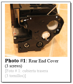
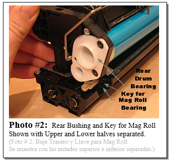
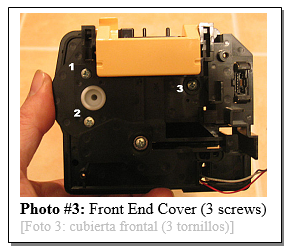
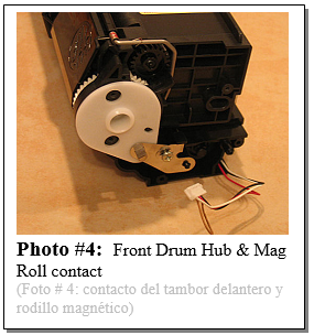
1. Remove the Front Cover (2 screws) and disconnect the connector for the Toner Sensor. 2. Remove the Rear End Cover (3 screw, see Photo #1). The white coupling for the mag roll drive will now fall right off for you. 3. Extract the rear white Drum / Mag Roll Bushing from the end of the drum (it is what joins the upper and lower halves at this point). This will allow you to separate the upper and lower halves of the rear end. Gently lift the upper half with the drum up a bit till you can re-insert the Drum Collar / Bushing into the drum while making it so that it remains liberated from the mag roll on the lower half (See Photo #2). 4. Remove the Inner Front Cover from the front (3 screws… see Photo #3). 5. Release the Front Drum Bearing’s Ground Contact (1 screw) and gently remove the contact from the front end of the D’-Shaped Mag Roll shaft. Then you can slide the front drum hub off . Lift the entire upper assembly up and re-insert the front Drum Hub to keep the drum secured. Be careful as both the front and rear Drum Hubs are now loosely inserted. (see Photo #4)
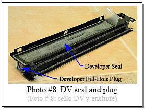
Now that you have the two halves of the cartridge separated, you’ll want to work on the bottom half (Developer and Pull-Seal) before you rebuild the top half (new Drum, Blade, Charge Roller, and CRUM chip). This is because the top half has the drum which is delicate and also light sensitive, so it’s better to leave it till last. Installing a Developer Pull-Seal will makes it possible to ship the rebuilt units when you’re done. Before the developer and seals were available, you could only rebuild the top half, and you would be forced to hand-deliver the cartridge. This was because turning the unit over with the developer free in the mixing area, and on the mag roll, could allow developer material to get out of the lower half. It could get into the drum, blade and charge roll area, and ruin your good work. It was also less than ideal not to be able to replace the developer material because the developer would eventually wear out sometime after the 2nd cycle. When you buy a new cartridge, the developer is in a compartment above the mixing augers. When your customer installs the new cartridge and pulls the seal, the developer drops down into the mixing area where it can get over to coat the mag roll. You’ll need to clean out the old developer, install the mylar peel-and-stick “Developer Pull-Seal, and pour the new shot of developer into the storage compartment.
PROCEDURE (part 2) – Lower Half:
PROCEDURE (part 3) – Upper Half (drum, charge, and cleaning):
5325/5330/5335 CRUM replacement: The 5325/5330/5335 use part number 13R591 (013R00591) which have a stated yield of 96K pages. This newer type of cartridge is extremely similar to its predecessors. Fortunately, the drums, blades, and charge rolls are all interchangeable. The Drum Reset CRUMs are of course different.
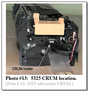
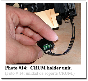
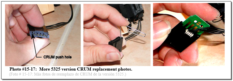
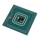
Instead of the RF CRUMs which were found in slots on the sides of the earlier C123 and 5225 cartridges, the new cartridges have CRUMs which are housed in the front end of the cartridges just behind the front cover. They slide into a little unit which has 4 spring contacts inside, and an intermediate board. Wires run to a rearward facing connector where contact is made with the machine (see Photo #13 & 14). To replace the 5325 version of the CRUM you need to first unseat the CRUM holder unit (it has two clips which keep it in place). Then you need to release the CRUM itself from its holder unit using your fingernail (or a small tool… be gentle) to pry the catch till you can slide the CRUM off. You may find it helpful to use the end of a paper clip to push the CRUM out (there is a small “CRUM push hole” at the far edge). Take note of how the CRUM is oriented… the 4 metal contacts need to be facing the other board and the 4 spring contacts inside the holder unit. It slides in with the end with the contacts sliding in first (see Photo # 15-17). As you can see, on the newest cartridges (the 5325 version), the CRUM chip can be replaced relatively easily by removing the front end cover. On the C123 and WC-5225 versions of the ctgs, if you ever need to replace the CRUM Chip, and don’t plan to go any deeper into the unit, you will need to create some room for it to slide out of its alcove. You can do so by releasing the rear Drum / Mag Roll Bushing, lift the rear up a little bit and reinstall the Drum Bushing to help protect the drum. The Chip will then have enough clearance to slide out all the way. The side of the chip which has the electronic components mounted on it should be facing inward. Be very careful not to touch or damage the components on the CRUM chips… they are very fragile and damaged CRUM components lead to a vast majority of problems in these cartridges.
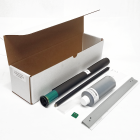
Drum Cartridge Rebuild Kits (includes drum, blade, charge roll, Developer, DV Pull-Seal, & CRUM chip):
Parts are also sold individually:
Here are a few of the Status Codes which relate to the Drum Cartridges…
I hope this is the start of something excellent for your business. These cartridges will likely become an important staple in your copier repair diet in the years to come. Repair and Enjoy!
|

